< |
Lazy Grain Boundaries |
> |
|
|
|
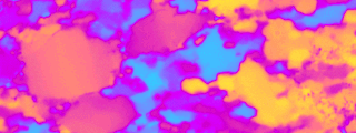
micrograph of quartzite with crossed polarizers and lambda plate
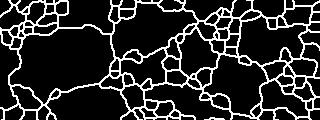
bitmap showing grains in black and grain boundaries in white
|
|
|
INTRODUCTION
The purpose of the Lazy Grain Boundaries macro is to identify grain boundaries on
a thin section, and to represent them in the form
of a grain map (in image processing, this is called
image segmentation).
The Lazy Grain Boundary
detection uses gray scale input images and it is
assumed that - in some way - the gray scales
represent different crystallographic orientations,
in the sense that a rapid change of
crystallographic orientation is portrayed by a
rapid change of gray value. For better results,
more than one image is used per area of analysis,
for example, various orientations of the
polarizer/analyzer with respect to the thin section
are used. Images are typically combined to a stack.
The basic idea is to combine the most
significant information from the different slices ("views")
rather than trying to get all information out of
one single image.
The procedure described in
the following uses misorientation images as input.
It is the "standard procedure" for quartzites. The
resulting grain boundary maps are designated by the
ending "cuogu-z-3tji" which is short for the
sequence of key strokes that are used to carry out
the segmentation. For most steps in the procedure,
a number of alternatives are possible. From my
experience, the "standard procedure" works best for
quartzites, for other rock types and other input
images, other combinations of key strokes may yield
better results (and maybe new macros have to be
written....).
|
|
|
|
|
GETTING STARTED
Load Lazy Grain Boundaries macro.
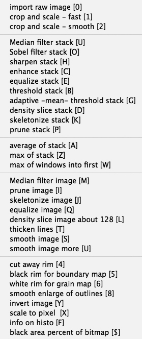
The macros are grouped in five groups according to their purpose:
- import images - resize and crop stack
- perform edge detection on all slices of stack
- combine information on one (average / best) image
- (post-)process image
- "beauty case": prepare grain map for analysis
|
|
|
|
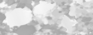
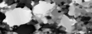
misorientation image:
gray values (0 - 90) indicate degrees misorientation
|
|
|
|
STEP 1
Open the misorientation
images misE, misN and misH (= images that result
from the CIP procedure: c-axis misorientation
images with respect to East, North and Heaven (or
Hell). Combine images to stack.
Stack of misorientation images
- .misE (from East),
- .misH (from "heaven" (=up)),
- .misN (from North)
Alternatively, color images (TIFF format) may be used,
the R-G-B channels will open as three slices of a stack.
|
|
|
|
Lazy Grain Boundaries:
[C] [U]
|
|
|
|
STEP 2
If the grains are very small
it may be advisable to use enlarged input images,
i.e., an enlarged input stack. [2] is used to
enlarge the stack by bilinear interpolation. After
segmentation the same routine is used in an inverse
sense to obtain the original image size. Contrast
enhancement [C] or median filtering [U] may
not always be necessary.
|
|
|
|
Lazy Grain Boundaries:
[C] [U] [O]
|
|
|
|
STEP 3
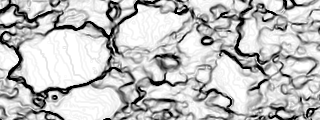
Edge detection [O] is by
the Sobel method. The Sobel edge detector is a well
established and safe edge detector which is very
widely used. More efficient edge detectors have
been designed recently, however, they are not (yet)
available on Image SXM.
|
|
|
|
Lazy Grain Boundaries:
[C] [U] [O] [G] [U]
|
|
|
|
STEP 4
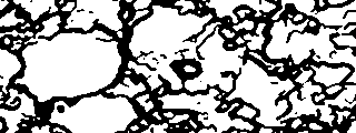
Adaptive thresholding [G]
performs a threshold on each of the slices of the
satck using the mean value of the histogram. Other
thresholds such as the mode of the histogram [V]
etc. or interactive thresholding can be
tried.
Additional median filtering is used to reduce noise.
|
|
|
|
Lazy Grain Boundaries:
[C] [U] [O] [G] [U] - [Z]
|
|
|
|
STEP 5
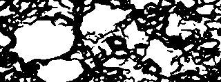
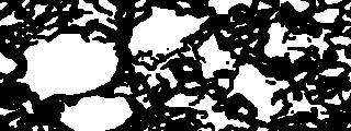
To combine the thesholded
slices of the stack into one image, image addition
by inclusive-or [Z] (calculation of maximum
image) is used here. It is possible to use other
modes, such as image averaging [A], but
addition by inclusive-or has proven to be the best
because it is sensitive to the slightest grain
boundaries found anywhere on any of the slices of
the stack.
(The stack is now reduced to one image.)
|
|
|
|
Lazy Grain Boundaries:
[C] [U] [O] [G] [U] - [Z] - [T]
|
|
|
|
STEP 6
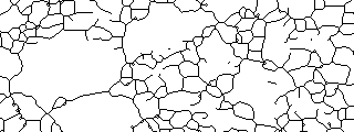
After combining the stack
into one image (by whatever method), the image is
thickened [T].
Thickenning is optional, see also steps 8 and 9.
|
|
|
|
Lazy Grain Boundaries:
[C] [U] [O] [G] [U] - [Z] - [T] [J]
|
|
|
|
STEP 7
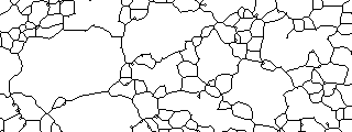
The image is skeletonized [J].
Note that careful noise cleaning is very useful:
during skeletonization thick solid outlines reduce to single outlines,
whereas white pixels on noisy outlines give rise to numerous (artifical) "bubble" grains.
|
|
|
|
Lazy Grain Boundaries:
[C] [U] [O] [G] [U] - [Z] - [T] [J] [I]
|
|
|
|
STEP 8
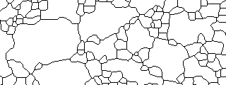
The image is pruned [I].
Loose ends and open boundaries are trimmed. It pays to carefully close outlines -
if necessary by hand - before this step is carried out.
Note that pruning cannot proceed around right-angled kinks nor across "bubble" grains
|
|
|
|
Lazy Grain Boundaries:
[C] [U] [O] [G] [U] - [Z] - [T] [J] [I] [T] [J] [I]
|
|
|
|
STEP 9
The image is thickened - skeletonized - pruned [T] [J] [I].
In order to to make kinks erodable and in order to close "bubble" grains, the outlines
are thickened, skeletonized and pruned again.
Note that these three steps should not be applied too often - else the
grain boundaries take on completely artificial shapes.
|
|
|
|

Lazy Grain Boundaries:
[C] [U] [O] [G] [U] - [Z] - [T] [J] [I] [T] [J] [I] - [T] [5] [Y]
|
|
|
|
STEP 10
The outlines are thickened [T] and the image is cropped [5] and inverted [Y].
Thickening is necessary because thin outlines are not recognized by
the Images SXM Analyze menu.
The rim is cut off because along the edge of the image, the grains show
artificial grain boundaries.
The bitmap is inverted to make the grains recognizable for the Image SXM Analyze menu.
|
|
|
|
(full size = 980 x 620)
|
|
|
|
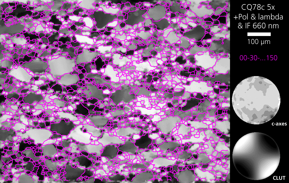
RESULTS
Input images =
6 rotation images taken
with
- crossed polarizers AND lambda-plate
rotated 0°, 30°, 60°,
90°, 120°, 150°,
- interference filter 660nm.
|
|
|
(full size = 980 x 620)
|
|
|
|
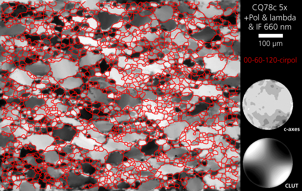
Input images =
3 rotation images taken
with
- crossed polarizers AND lambda-plate
rotated 0°, 60°,
120°,
- interference filter 660nm.
1 image taken with
- circular polarization (= two quarter wave plates)
- interference filter 660nm.
|
|
|
(full size = 980 x 620)
|
|
|
|
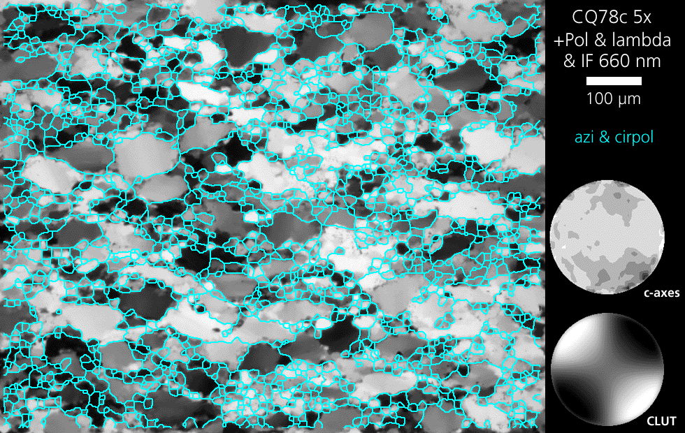
Input images =
2 CIP output images:
- 1 azimuth image,
- 1 primary inclination image (= circular polarization)
|
|
|
(full size = 980 x 620)
|
|
|
|
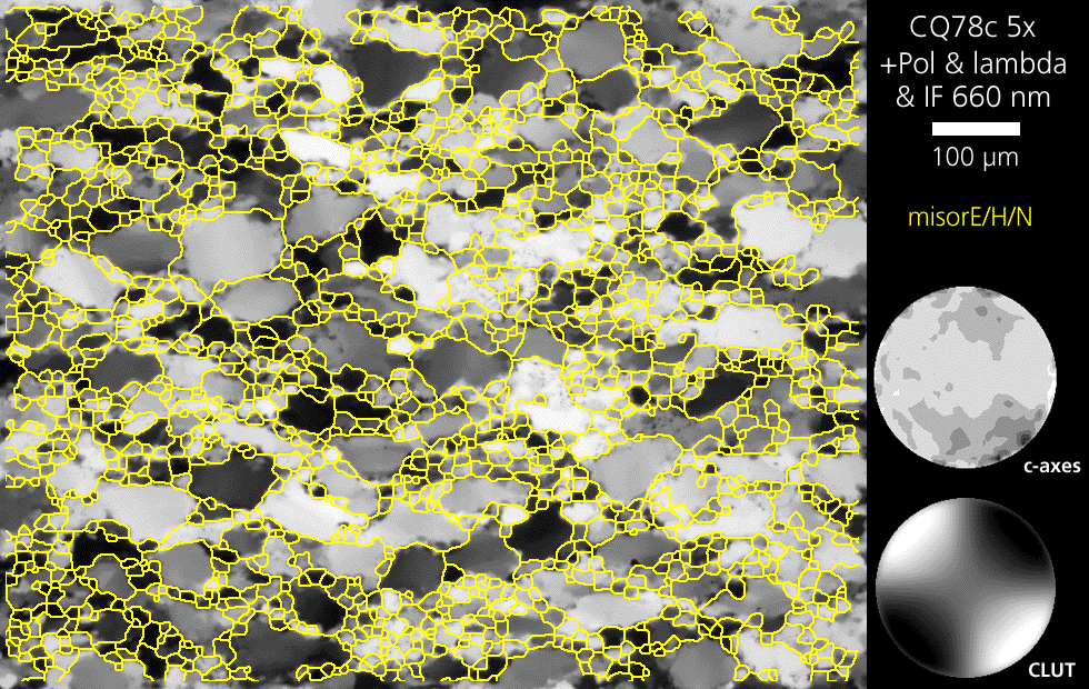
Input images =
3 CIP output images:
- misE: misorientation with respect to East,
- misN: misorientation with respect to North,
- misH: misorientation with respect to Heaven (Up),
i.e. with respect to horizontal axis, vertical
axis and axis normal to image plane.
|
|
|
(full size = 980 x 620)
|
|
|
|
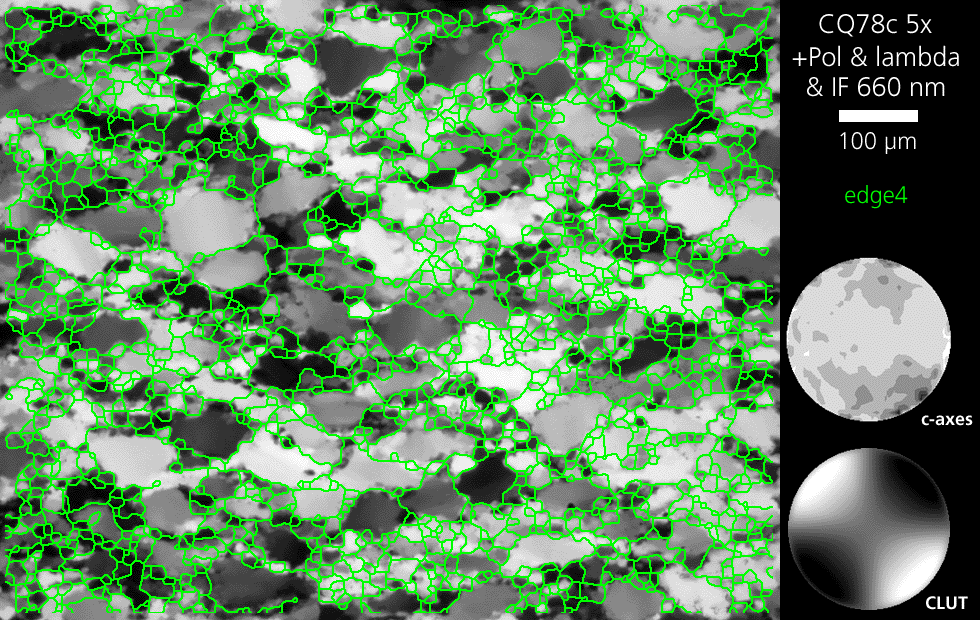
Input images =
1 CIP output image:
- orientation gradient image with respect to 4 neighbour pixels
|


