< |
Lazy LUTs |
> |
|||||||||||||
|
|
|
INTRODUCTIONThe Lazy LUTs macros are intended to provide a quick introduction to the concept of look-up tables. At the same time, because they are very simple and easily edited, the serve as an introduction to Image SXM macro programming. |
||||||||||||
|
|
|
GETTING STARTED
Load Lazy LUTs macro.
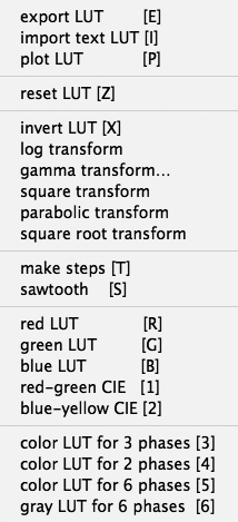
The macros are grouped as follows:
|
||||||||||||
|
|
|
IMPORTING EXPORTING PLOTTING
Look-up tables (LUT) can be loaded from the Options menu of Image SXM.
|
||||||||||||
|
|
|
LUT FUNCTIONS
An example of a very simple function is given here:
macro 'invert LUT [X]'; var i:integer; begin for i:=0 to 255 do begin RedLUT[i]:=255-RedLut[i]; GreenLUT[i]:=255-GreenLut[i]; BlueLUT[i]:=255-BlueLut[i]; end; UpdateLUT; end;
|
||||||||||||
|
|
|
SIGNIFICANT BIT REMOVAL
Using 1 byte = 8 bit to encode grey values yields 256 different values.
If 1 bit is removed, i.e., if only 7 are used, only 128 GV are possible, etc.
Bits can be removed from either end of the byte:
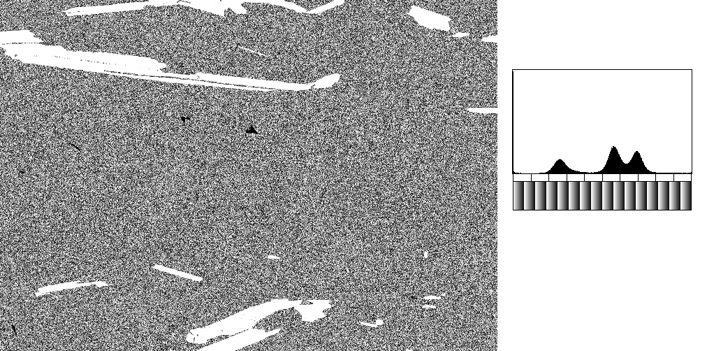
removing the least significant bit yields 2, 4, 8, 16 etc. steps;
removing the most signifcant bit yields 2, 4, 8, 16 etc. ramps.
|
||||||||||||
|
|
|
COLOR CHANNELS
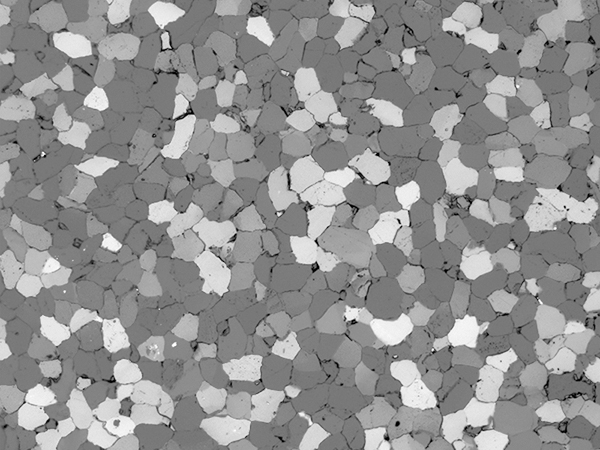
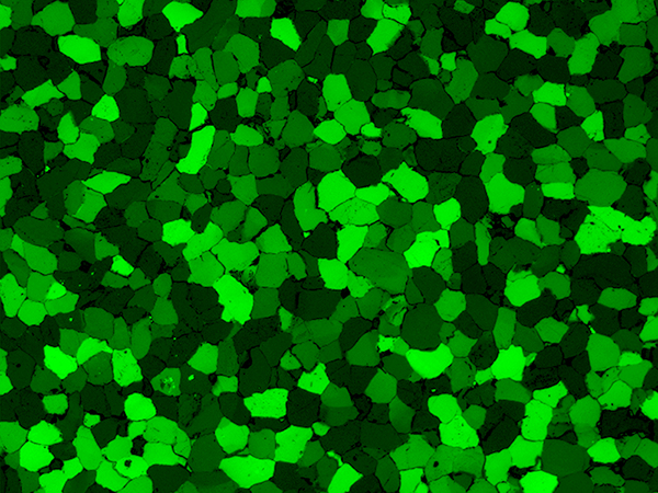
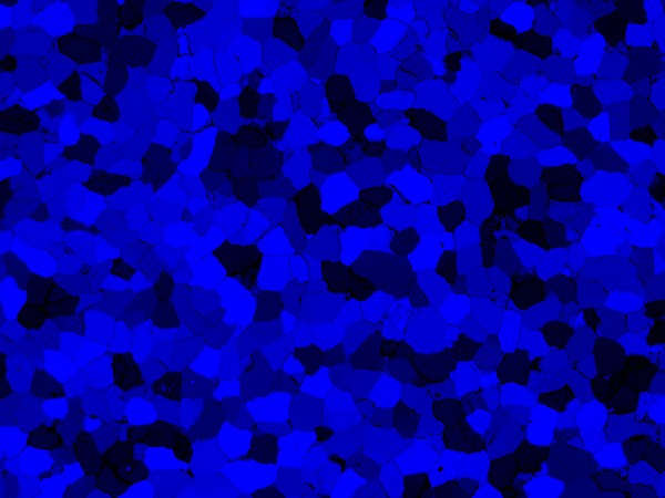
This set of LUT macros serves to render color channels in the appropriate color.
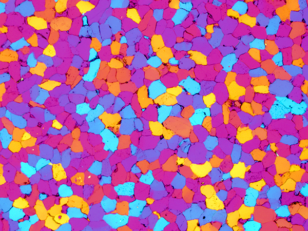
Image SXM does open color images - they are converted to an R-G-B stack
and an index image is displayed - with the System LUT loaded - to give a color impression.
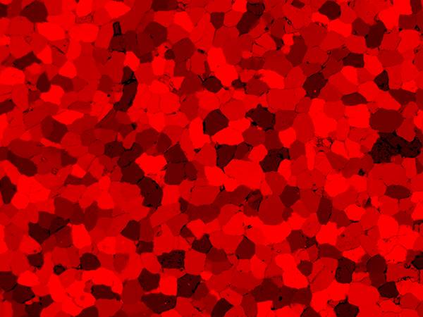
If the image is RGB, the slices of the stack contain the corresponding channels Red, Green and Blue.
If the image is Lab, the slices contain L(brightness), a(red-gren), b(yellow-blue).
|
||||||||||||
|
|
|
SEGMENTATION
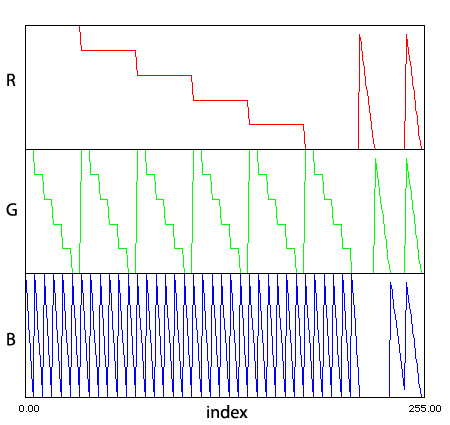
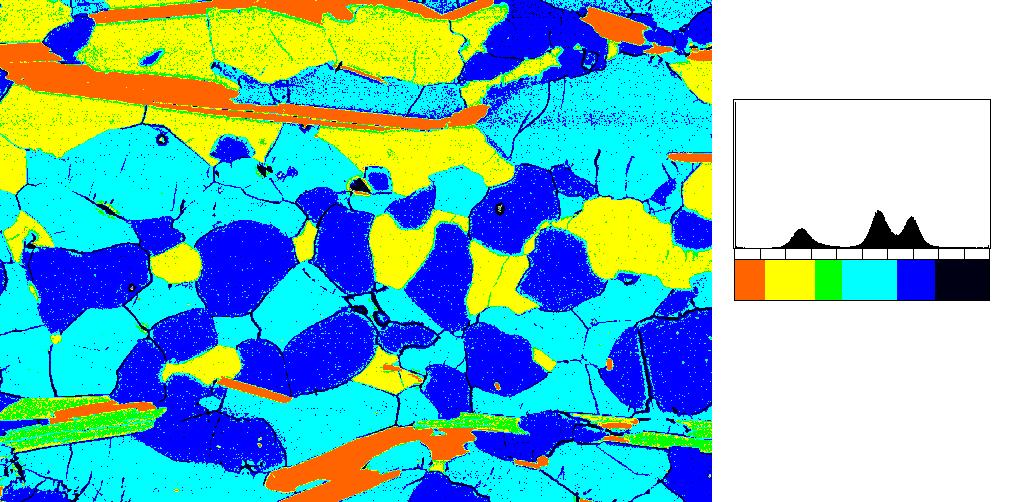
Look-up tables correspond to point operations.
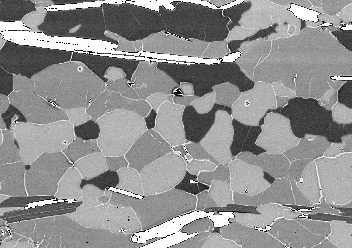
LUTs can therefore be used to segment images by combining ranges of gray value
(grey level slicing)
Once the LUT is applied, the image is effectively segmented.
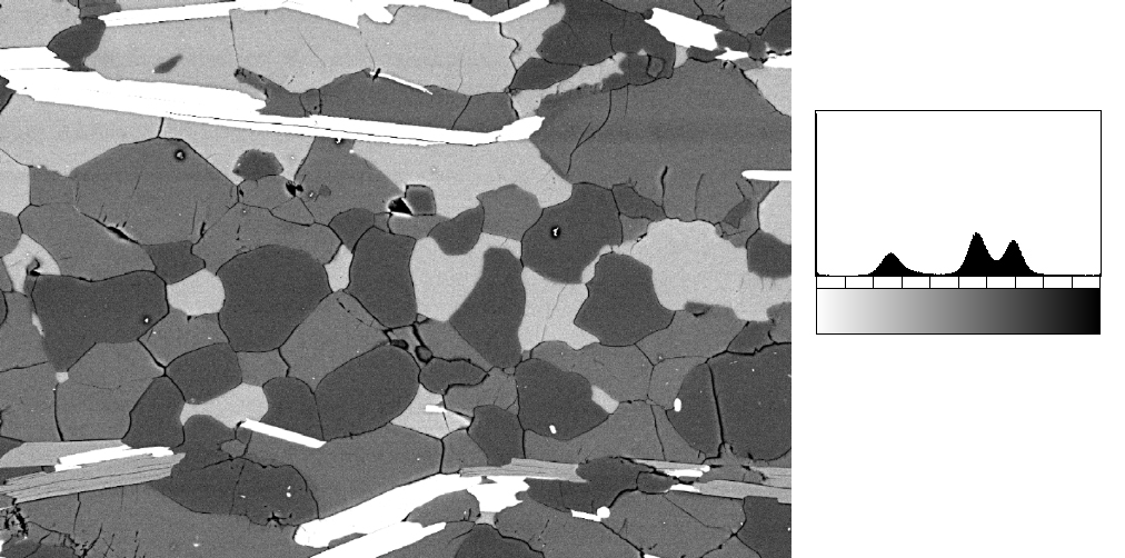
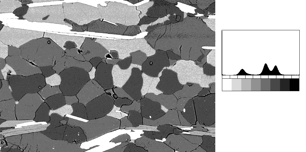
Here, the histogram of grey values is used to determine the limits of the grey level slices.
|
||||||||||||
