< |
Lazy Prepstack |
> |
|
|
|
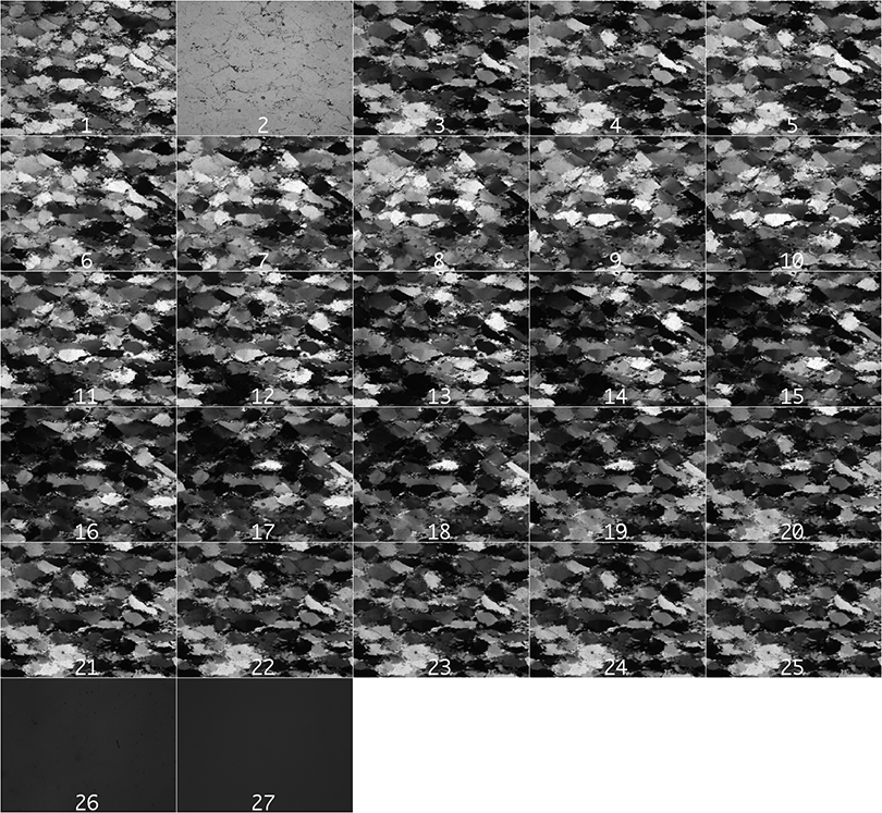
INPUT IMAGES
- cirpol
- nopol
- rot.000
- rot.010
- rot.020
- rot.030
- rot.040
- rot.050
- rot.060
- rot.070
- rot.080
- rot.090
- rot.100
- rot.110
- rot.120
- rot.130
- rot.140
- rot.150
- rot.160
- rot.170
- rot.180
- eup
- sup
- wup
- nup
- backFlat
- backTilt
|
|
| |
|
|
INTRODUCTION
The Lazy PrepStack macros are intended to facilitate the assembling the input for CIP
and/or PrinCIPia calculations (more about this method here).
For CIP calculations the images musst be saved in RAW format
- they are best assembled in a folder (input folder)
(more about CIP input here).
|
|
|
|
|
GETTING STARTED
Load the Lazy PrepStack macro.
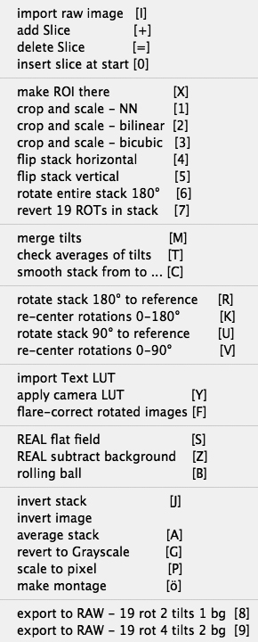
The macros allow you to do the following:
- import/open images and compile stack
- crop, re-size, flip, rotate, re-arrange the stack
- prepare tilt images
- re-rotate and register rotation and polarization images
- make camera corrections
- subtract background
- additional editing
- export slices of stack to RAW image for processing with CIP
|
|
|
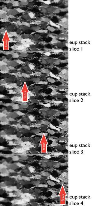
4 slices of East-Up stack with shifted focus
|
|
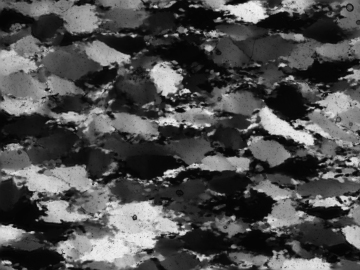
[M] composite made by merging stack
|
|
|
PREPARE TILT IMAGES
To obtain tilt images, the section is tilted by up to 5°, as a consequence,
the image is not parallel to the focus plane anymore.
Depending on the magnification, it may be necessary to take 3 to 5 exposures
at increasing distances within the range of the depth of focus.
These images have to be combined to yield one image per tilt
- [M] merges tilt images in tilt stack using the Depth of Focus command
- [T] checks that the average gray value is the same in all tilt images and in the last of the rotation images (.rot180)
- [C] performs a smoothing filter on the tilt images and on rot180.
|
|
|
|
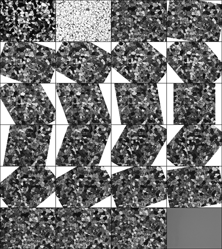
Stack with back-rotated rotation images
| |
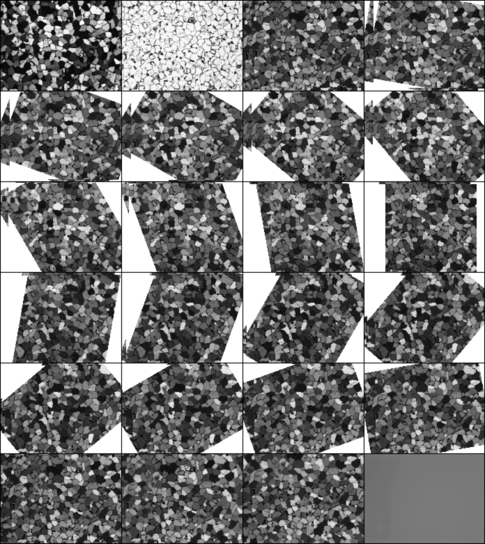
Stack with registered back-rotated rotation images
|
|
|
|
REGISTER ROTATIONS
If the rotation images were taken with a rotating microscope table,
the images (slices in a stack) need to be rotated to the starting orientation
The procedure consists of the following steps:
- rotation of the slices about the image center
(→ in most cases the center of the image is not the center of rotation of the microscope)
- bringing images into registry
- a semi-circular path of the center of rotation in the images is assumed
|
|
|
|
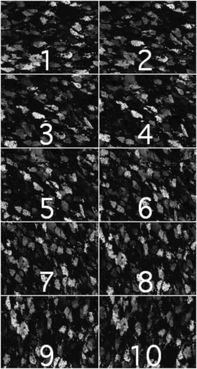
Stack of crossed polarization
| |
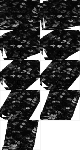
Matched stack of crossed polarization
|
|
|
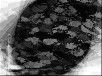
Average of crossed polarization
| |
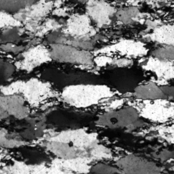
Enhanced and cropped average
= digital cirpol
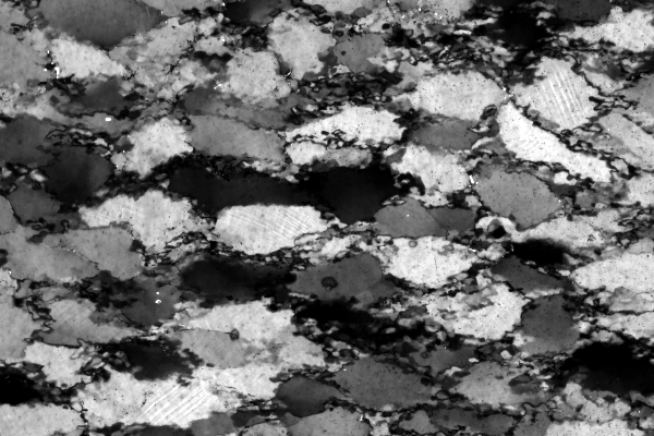
Original cirpol
|
|
|
|
DIGITAL CIRPOL
If circular polarization is not available, the following procedure can be adopted
to create a cirpol image by digital means.
- use 10 cross polarized images taken at regular intervals of orientation between 0° and 90°
- rotate all into superposition
- register the rotated images
- remove last slice (to avoid duplication of 0° and 90° orientation
- average of stack (p slices) yields circular polarization
- crop to overlapping area
- enhance contrast
|
|
|
|
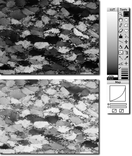
Uncalibrated and calibrated stack. Palette with camera LUT on right.
|
|
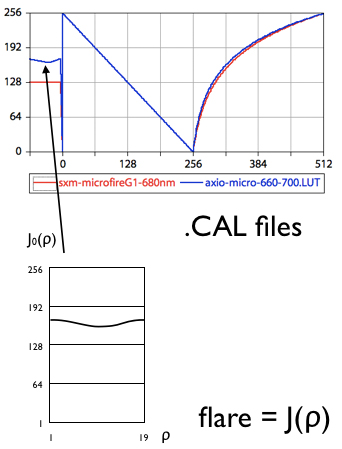
[F] Correcting for uneven illumination due to rotating polarizers.
|
|
|
|
CAMERA AND LIGHTING
Camera and lighting corrections are usually carried out in CIP or PrinCIPia.
However it is possible to explicitly perform the corrections on the input stack.
In this case, the settings in the control files (.ctrlA and .ctrlB) have to be set accordingly.
If [Y] is used, a special camera.CAL file (with 1:1 'calibration') has to be provided.
2c) Corrections ROT-bg,CIRPOL-bg,FLARE,cirpol-camera? (0=don't 1=do)
1,1,0,0
- import LUT as text file (text file = camera calibration function)
- [Y] apply camera LUT: uses Palette with camera calibration
- [F] flare correction: brighthness variation as f(rotation of polarizer) has to be known
|
|
|
|
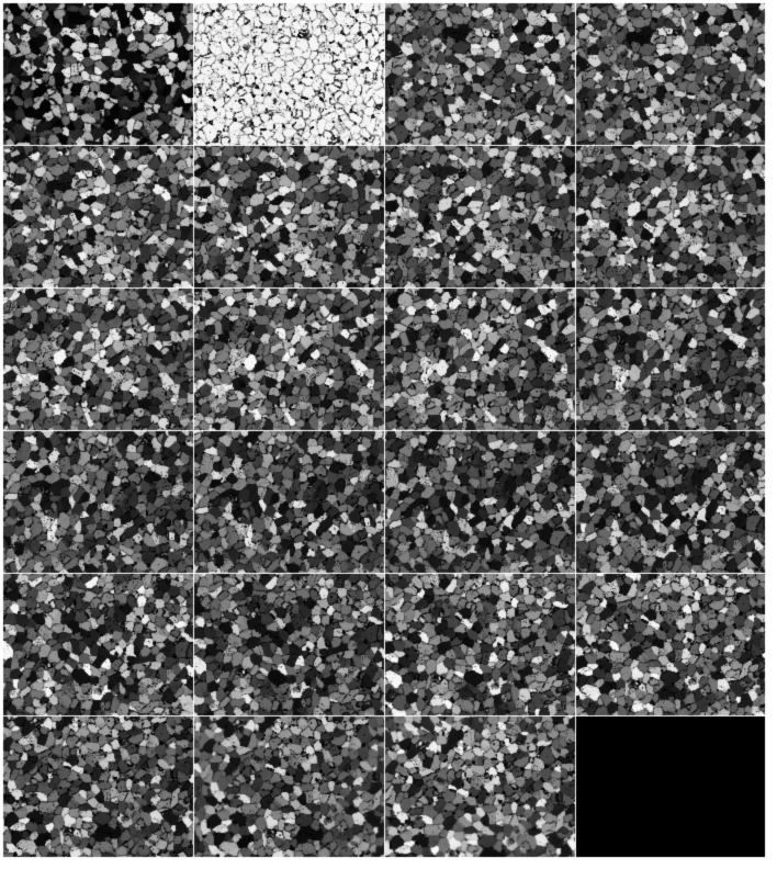
[S] Stack divided by background
|

[Z] Stack with background subtracted
|
|
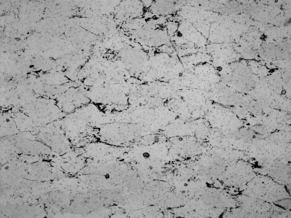
nopol image
|
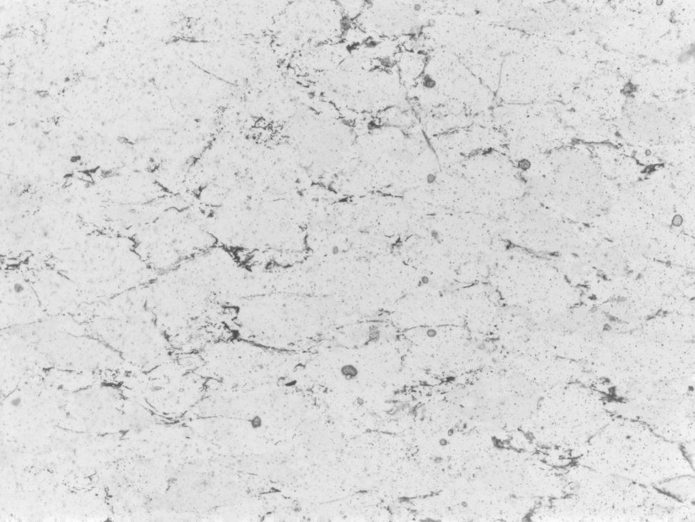
[B] rolling ball background subtraction
|
|
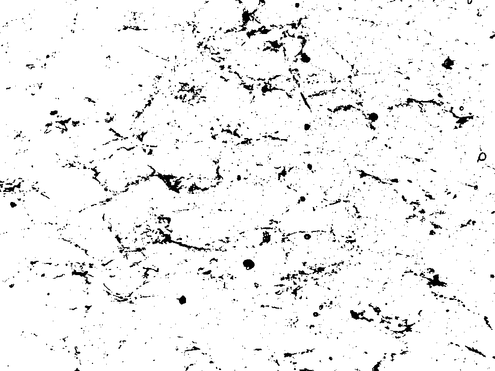
thresholded
|
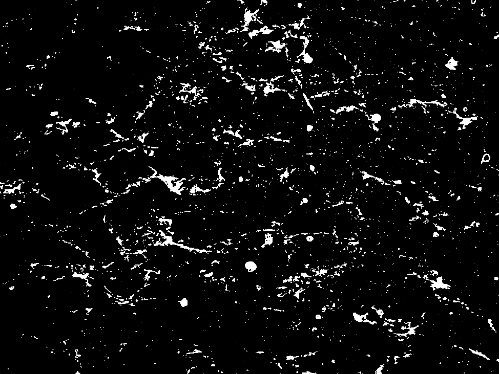
white mask
|
|
|
SUBTRACT BACKGROUND
Background corrections are usually carried out in CIP or PrinCIPia.
However it is possible to explicitly perform the corrections on the input stack.
In this case, the settings in the control files (.ctrlA and .ctrlB) have to be set accordingly.
2c) Corrections ROT-bg,CIRPOL-bg,FLARE,cirpol-camera? (0=don't 1=do)
0,0,1,1
- [S] real flat field: using background image
- [Z] real subtract background: using background image - requires calibration
- [B] rolling ball: no background image required
|
|
|
|
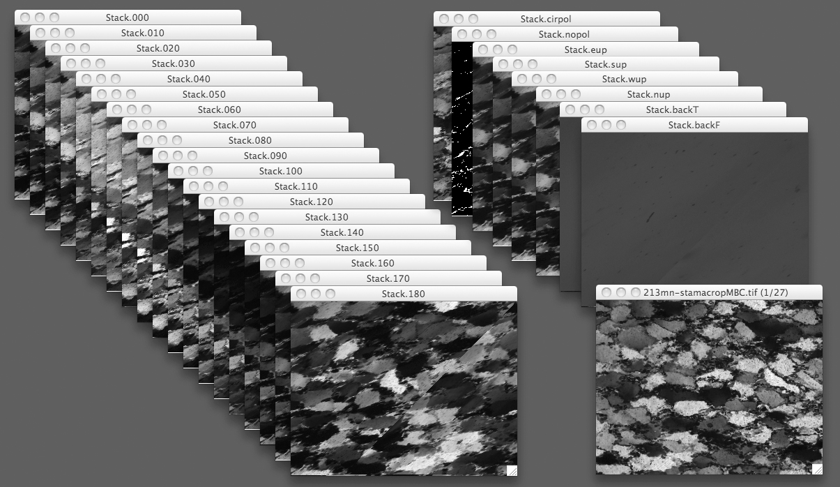
[9] slices of stack exported to RAW images
|
|
|
|
EXPORT STACK
For CIP calculations the inout has to be in RAW format.
- [8] export 24 slices of stack with 2 tilts and 1 background image
- [9] export 28 slices of stack with 4 tilts and 2 background images
|

